MG Rover Rover 200/25 and MG ZR Vehicle Information
Model Range Overview
Vehicle Identification Plate
The Vehicle Identification (VIN) Plate is located at the foot of the left hand door pillar and contains a series of number and codes that define each individual vehicle. The content is illustrated below.
Vehicle Identification Numbering System
The Vehicle Identification Number (VIN) comprises a series of letters and numbers representing, in code, the World Make Identifier, Marque, Model, Class, Body, Engine, Transmission, Steering, Model Change, Assembly Plant and Serial Number applicable to each individual vehicle (effective from November 1998). This number should be quoted in full when communicating with your dealer. The VIN number can be found on the VIN plate (at the foot of the left hand door pillar), stamped into the centre of the bulkhead (at the top inside the engine compartment), and on a plate visible through the bottom left hand corner of the windscreen.
SAR RF H N L B X D 100001
The 1st, 2nd, and 3rd letters represent the World Make Identifier.
SAR RF H N L B X D 100001
The 4th and 5th letters represent the Marque and Model, in this case RF = Rover 200/25 and MG ZR.
SAR RF H N L B X D 100001
The 6th letter represents the Class of vehicle eg:
C = 200 BRM
D = Streetwise (RO)
H = 200, 214i, 220D (CO)
J = 200 (S2)
K = Streetwise (R1)
L = MG (M2)
M = 200, 214Si, 216Si, 220SD, 220SKi, 200 (C1)
N = 200 (TL 3.1)
P = Streetwise (R2)
W = 200Vi, 200 (S1)
X = MG (MO)
Y = 200, 216SLi, 216Si (LHD), 220SDi (LHD), 200 (Y2)
Z = 200 (C3)
SAR RF H N L B X D 100001
The 7th letter represents the Body eg:
F = 3 Door Van
N = 3 Door
W = 5 Door
SAR RF H N L B X D 100001
The 8th letter represents the Engine eg:
A = 1400P 16V MPi-LP Petrol
B = 1400P 16V MPi-HP Petrol
C = 1100 16V MPi Petrol
D = 1100 16V MPi Petrol
E = 1600 16V MPi Petrol
F = 1800 16V MPi Petrol
G = 1800 16V MPi Petrol
H = 1400 16V Petrol
K = 1800 16V VVC (143) Petrol
M = 1800 16V VVC (160) Petrol
N = 2000 8V TCie Turbo Diesel
P = 1400 8V Petrol
W = 2000 TCie Turbo Diesel
X = 2000 TCie-M Diesel
Z = 1600 16V Petrol
SAR RF H N L B X D 100001
The 9th letter represents the Transmission/Steering eg:
B = Manual 5-Speed, RHD M = Manual 5-Speed, LHD
C = Manual 5-Speed, RHD N = Manual 5-Speed, LHD
D = Manual 5-Speed, RHD P = Manual 5-Speed, LHD
E = Manual 5-Speed, RHD R = Manual 5-Speed, LHD
F = Manual 5-Speed, RHD S = 2Manual 5-Speed, LHD
G = Manual 5-Speed, RHD T = Manual 5-Speed, LHD
H = Manual 5-Speed, RHD V = Manual 5-Speed, LHD
J = Automatic CVT, RHD X = Automatic CVT, LHD
L = Automatic CVT, RHD Z = Automatic CVT, LHD
SAR RF H N L B X D 100001
The 10th letter represents the Model Change Point eg:
W = 1998 Model Year
X = 1999 Model Year
Y = 2000 Model Year
1 = 2001 Model Year
2 = 2002 Model Year
3 = 2003 Model Year
4 = 2004 Model Year.
5 = 2005 Model Year etc.
SAR RF H N L B X D 100001
The 11th letter represents the Assembly Plant eg:
D = Longbride
SAR RF H N L B X D 100001
The remaining digits are the vehicle Serial Number. The Rover 200 Series ran until Serial Number 471564.
Engine Identification Number Location
Petrol Engine Identification Codes
The engine number comprises a series of letters and numbers presenting in code the cubic capacity, the ancillaries fitted and the type of compression. This page describes the 1st and 2nd prefix groups, the 3rd prefix group is described on the following pages. The engine serial number is a unique number. Refer to the EPC for a complete listing of Engine Number codes. Always quote the prefixes with the engine serial number.
The engine number comprises a series of letters and numbers presenting in code the cubic capacity, the ancillaries fitted and the type of compression. This page describes the 3rd prefix group, the engine serial number is a unique number. Refer to the EPC for a complete listing of Engine Number codes. Always quote the prefixes with the engine serial number.
The engine number comprises a series of letters and numbers presenting in code the cubic capacity, the ancillaries fitted and the type of compression. This page describes the 1st and 2nd prefix groups, the 3rd prefix group is described on the following pages. The engine serial number is a unique number. Refer to the EPC for a complete listing of Engine Number codes. Always quote the prefixes with the engine serial number.
The engine number comprises a series of letters and numbers presenting in code the cubic capacity, the ancillaries fitted and the type of compression. This page describes the 1st and 2nd prefix groups, the 3rd prefix group is described on the following pages. The engine serial number is a unique number. Refer to the EPC for a complete listing of Engine Number codes. Always quote the prefixes with the engine serial number.
Diesel Engine Identification Codes
The engine number comprises a series of letters and numbers presenting in code the cubic capacity, the ancillaries fitted and the type of compression. The engine serial number is a unique number. Always quote the prefixes with the engine serial number.
Transmission Identification Number Location
Transmission Identification Number Code
The transmission number comprises a series of letters and numbers presenting in code the number of gearbox speeds, gearbox ratio type, final drive ratio, speedo ratio. The transmission serial no. is a suffix to the transmission number shown.
Body Identification Number Location
The Body Identification Number is stamped on a metal plate located in the boot to the left of the spare wheel housing and beneath the floor trim panel.
Body Colour Identification Codes
The (VIN Plate (see Vechile Identificatione Plate) includes codes to accurately identify body paint colours. These codes and colour names should always be used when ordering replacement parts. The codes and colour names shown are related to those in the vehicle colour charts and the Rover Paint Refinishing Manual.
Rover 25 Main Trim Colour Combinations
The VIN Plate (see Vehicle Identification Plate) includes the Interior Trim Feature Code to accurately identify colour ways used for the vehicle trim. The Part Suffix Code is appended to the specific seat part number to define the seat type and colour. When ordering replacement parts the interior trim colours should be specified using the codes and colour names given below. These are the recommended colour combinations.
Rover 25 Monogram Trim Colour Combinations
The VIN Plate (see Vehicle Identification Plate) includes the Interior Trim Feature Code to accurately identify colour ways used for the vehicle trim. The Part Suffix Code is appended to the specific seat part number to define the seat type and colour. When ordering replacement parts the interior trim colours should be specified using the codes and colour names given below. These are the recommended colour combinations.
MGZR Trim Colour Combinations
The VIN Plate (see Vehicle Identification Plate) includes the Interior Trim Feature Code to accurately identify colour ways used for the vehicle trim. The Part Suffix Code is appended to the specific seat part number to define the seat type and colour. When ordering replacement parts the interior trim colours should be specified using the codes and colour names given below. These are the recommended colour combinations. Seat options marked * are available on the MG Express van. Refer to the EPC for a complete listing of all codes used on MGZR vehicles.
Airbag Deployment - Parts Replacement Policy
Supplementary Restraint Systems
Driver airbags are fitted as standard on the Rover 25 and derivatives, passenger airbags are available as an option. Front seatbelt pretensioners are fitted to all vehicles. The service life of components incorporated into the SRS system is 15 years. After this time the components must be replaced. The following information details the policy for replacement of SRS components, either as a result of a vehicle accident or as a result of vehicle age.
Impacts Which Deploy The Airbags Or Pretensioners
The replacement policy is dependent on the type and severity of the crash condition. The following guidelines are a minimum that should be exercised as a result of the deployment of specific SRS components.
Front Airbag Deployment- Driver and Passenger
When the system deploys the following parts must be replaced:
Driver Airbag Module
Passenger Airbag Module (where fitted)
Flyleads (where applicable) connecting the Front Airbag Modules to the SRS Harness
Front Seat Belt Buckle Pretensioners
Drivers Seat Belt Retractor
Steering Wheel Rotary Coupler
SRS DCU
Note that there is no requirement to replace the SRS Harness which is integrated into the Main Vehicle Harness, it is allowed to be repaired in service.
In addition the following parts should be inspected for damage and replaced as necessary:
Front Passengers Seat Belt Retractor (webbing, tongue latching, 'D' loop, body anchorage point)
Rear Seat Belt Buckles (webbing, buckle covers, body anchorage and tongue latching function)
Fascia Moulding adjacent to Passenger Airbag Module (where fitted)
Steering Wheel (if damage is evident)
Front Seat Frames and Head Restraints (if there is evidence of damage to the seat frame or cushion pan)
Steering Column (if adjustment is lost or there are signs of collapse)
Rear Impacts
Rear impacts may cause the Seat Belt Pretensioners to deploy. If this happens, all Pretensioner Units must be replaced. In addition, the following components must be inspected for damage and replaced as necessary:
Front Seat Frames
Front Seat Belts (retractors, webbing, tongue latching, 'D' loop and body anchorage points)
Rear Seat Belt Buckles (webbing, buckle covers, tongue latching and body anchorage)
SRS DCU
Periodic Replacement Of SRS Components
The performance of the propellants within airbags and pretensioners will deteriorate over a period of time. As a result, it is essential that the airbags and pretensioners are periodically replaced to maintain occupant safety. Airbags, seat belt pretensioners and the rotary coupler should be replaced at 15 year intervals.
Spring and Damper Identification Label
Road Springs and Dampers are dependent on vehicle specification. Road Springs can be identified by a colour code - painted on the coils of the spring. Dampers can be identified by a colour code - painted on the damper body, they are not handed.
Key and Lock Information
When a new vehicle is supplied the key number can be found stamped onto a tag attached to the key ring.
The key number should be entered on the vehicle Security Information card by the owner.
The key number can be used to order vehicle specific locks. If the key number is not available then non-specific keys and locks must be ordered, in this case complete vehicle sets will be required to enable one key to fit all the vehicle locks. Alternatively multiple keys will be required for the vehicle. MG Rover use the following suffixes to identify specific and non-specific locks.
Rover and MG keys can be distinguished by individual logo's used on them and the distinctive octagonal shape of the MG key grip.
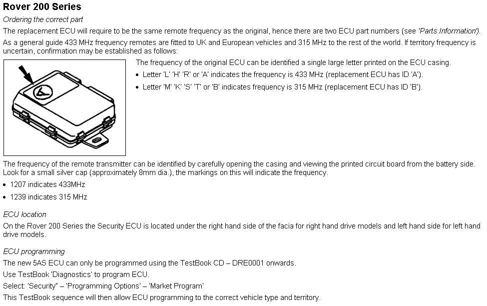
Security ECU Programming
Rover 200 Series
Affected Range
All vehicles fitted with Lucas 5AS Security ECU's.
Problem
Security ECU Programming – Parts Change.
The introduction of a new non-programmed ECU may initially cause part ordering confusion. Technicians may also be unfamiliar with the correct programming technique.
Cause
Previously, many pre-programmed ECU's were required to cover a variety of models and territories resulting in parts ordering and stocking problems.
Action
Two new 'non-programmed' ECU's have been introduced allowing many model versions and territories to be programmed from the same ECU.
The new ECU can only be fitted to vehicles having the latest Lucas 5AS security ECU.
Identification of vehicles having Lucas 5AS ECU is as follows
• Check the vehicle has a Lucas 5AS ECU fitted
• The latest Lucas 5AS ECU has two connectors, one grey 26 way and one white 12 way (the white connector is unused on some models).
Rover 200 Series
Confirmation that the ECU has been programmed
If the ECU has not been successfully programmed a 'Not Market Programmed' warning will sound when the vehicle ignition is turned on. This warning consists of the following:
A few seconds of the usual engine immobilised 'two-tone' chime, followed by a few seconds of silence and then a repeat of the chime etc.
This will sound regardless of immobiliser cancellation with remote.
When the ECU has been programmed to the relevant market the warning chime will cease.
Re-programming
If an error occurs during programming, the same ECU may be re-programmed more than once.
Parts information
Please refer to the EPC for the latest part numbers applicable to ECU 433 MHz (identification code 'A'), ECU 315 MHz (identification code 'B')
For vehicles prior to the introduction of the Lucas 5AS Security ECU, part numbers remain unchanged.
Warranty claims
Refer to the original cause of ECU failure and apply warranty claim as appropriate.
Rover 25 and MG ZR
Affected Range
Applicable to selected vehicles only, dealers affected have been informed.
Problem
Current ZCS code incompatible with 'Superlocking'.
Cause
A limited number of vehicles only fitted with the latest 'Superlocking' functionality have been found to be incompatible with the existing ZCS code. On these vehicles only, 'Superlocking' will be disabled if T4 / TestBook is used to Market Program the security (5AS) ECU.
Action
To prevent this condition occurring in the future, a change to the ZCS code is required on affected vehicles only.
• Apply the described action only if the vehicle VIN was on the list of affected vehicles
• Follow the instructions below to reset the ZCS code
• Market Program the 5AS Security ECU
• Confirm that 'Superlocking' is enabled
Procedure
1. Turn ignition 'OFF'
2. Disconnect the connector from the engine control module (see repair number 18.30.01 for location)
3. Connect T4 / TestBook with the latest diagnostic CD installed, ie. DJR0009 (Rover 25) or DRM0017 (MG ZR)
4. Turn ignition 'ON'
5. Select 'DIAGNOSTICS SYSTEM' from menu
6. Enter VIN when prompted
7. T4 / TestBook asks if information on screen is correct, select 'NO'
8. Select 'ENTER DATA MANUALLY'
9. Switch ignition 'OFF'
10. Re-connect the engine management ECM
11. Turn ignition 'ON'
12. Enter the ZCS code provided on the attached list, ie.
13. GM.....
14. SA......
15. VN......
16. When TestBook has completed reconfiguring vehicle ECUs, select 'SECURITY CONFIGURATION' from the 'VEHICLE CONFIGURATION' screen
17. Change to Yellow lead when prompted
18. Select market, either 'REST OF WORLD' or 'UK'
19. Follow on screen prompt until TestBook / T4 returns to the 'VEHICLE CONFIGURATION' page
20. Switch ignition 'OFF' and disconnect T4 / TestBook
To confirm that 'Superlocking' has now been activated successfully, carry out the following test:
• Press the handset lock button twice within one second
• The direction indicator lights flash once and then three more times to confirm that 'Superlocking' has been activated, the anti-theft alarm indicator light (in the instrument panel) starts to flash
' If the direction indicators fail to flash, this indicates a mislock
Customer Contact
It is important that this action is carried out prior to sale
Warranty Claims
Please submit warranty claims within 24 hours of completion of this exercise.
Use complaint code: 7G1U
Quote S.R.O. 18.90.40/01 this will credit you with 0.40 hours labour
Core Return Guide
The normal MG Rover returns process applies when returning worn material.
A worn core return request must be made within 180 days from the date of the invoice. This applies to both stock and VOR orders.
When a new or exchange part is purchased a surcharge will form part of the overall purchase price. All parts within this catalogue are issued with a surcharge.
This means to be able to receive a surcharge credit you must return your old worn material. By doing so we can guarantee the continuation of the remanufacturing process. Therefore worn core returns should be requested when you want to return your old worn material.
For any worn core material to be returned it must meet the following core return guidelines:
• The material must be acceptable for reconditioning (no fire damage).
• The material must be of MG Rover origin.
• The material is returned within its 180-day return period.
• The material is clean and drained of oil where appropriate.
• A return request must be raised using a ZRTN 110 return code.
• A return tag will be issued when the return request has been validated.
• Dealers must attach the return tag giving entitlement to make a return.
• Items requested for return, as part of a Warranty Claim, must be returned to MG Rover Warranty Returns. These items must have both the Warranty Returns Label and Warranty Surcharge Return Tag attached to the material being returned.
Surcharge credit will not be issued against returned worn core material if it has been broken, damaged, dented, or has missing parts. Photographic guidelines for each product range can be found in sections 4-11.
Note Should the rejected material be returned to you, there may be additional transportation costs incurred.
Note In the event that you would like to return a Worn Core Surcharge Unit that is outside the claim criteria or has not been purchased as part of the MG Rover Exchange programme you should contact MG Rover Customer Support who will be able to assist.
'Please note XPart (A Division of Caterpillar Logistic Services UK Limited) reserve the right to add an additional Surcharge to both new and Exchange parts, where the old product can be used to support current or future remanufactured product development'
Supersession information between Iovox units and Siemens units